Statement of Problem
Occasionally a field engineer will need to quickly measure the frequency of periodic signals. These signals could be in square, sinusoidal, or triangle form. Certainly there are labs with the proper devices that can measure these signals. However it is costly, not portable, and needs an AC power source. We will design and provide a portable, cheap, handheld device to overcome these problems. Our device will work on battery power and contain a built in function that will permit the device to shift into a power save mode when not in use. This will allow for battery life optimization.
The device will be able to measure frequency inside the range of 1 Hz to 100 kHz. The processing time will be within one second and allow the field engineer to maintain a constant monitoring of the frequency. The output display will be on an LCD screen which allows the end user to monitor frequency fluctuations at a constant and consistent rate.
Design Objectives
The heart of our frequency meter is a microcontroller Atmel ATTiny 2313 which will measure frequency by counting pulses within a certain time period. If the frequency being measured is less than 1000 Hz, it will measure the time in between pulses.
The data we are reading will be displayed on LED/LCD screen. Due to the low power consumption of the microcontroller and LCD, we can use AA batteries for a power supply.
Technical Approach
Our frequency meter (or “device”), contains four functional parts: analog, digital, a display and a power supply. The purpose of the analog part of the device is to convert analog periodic signals into a digital signal with the same frequency. The digital block measures the frequency of this signal and converts it into readable form and sends it to the display. The power supply provides +5V to power the device. Here is a description of each functional block.
The analog block is a simple zero-level cross detector. It uses an op amp as the core chip. We need low power, a single power supply comparator/operational amplifier just because our device is battery-powered. After careful selection, we choose the LM339 opamp from STMicroelectronics. This chip contains four op amps in one casing. It has a very good power consumption characteristic, thus it is very good for our device. Low price, low power consumption and low voltage supply makes it perfect a match. In our device we used recommended schematics from a typical application section from the manufactures’ datasheet. Also, the chip was included in our toolkits so it lowers prototype price. Other chips we tried were an LM741 op amp, and a MCP6142 low-voltage op amp. They didn’t show satisfactory results with voltage or with output signal quality.
The digital part is designed using an Atmel ATTiny 2313 microprocessor. To measure frequency it counts the amount of pulses within one second, the value of frequency is in Hertz. To count pulses the microcontroller uses an external interrupt. Every time when the AVR senses the front raise on pin then ISR (interrupt service request) is being generated. What we needed is for it to count the interrupts within a certain period of time, ideally within 1 second so we didn’t need to perform any calculations. Initially we used internal 8 MHz RC generator for the clock, but it didn’t give us sufficient accuracy. It was also very dependent on temperature. To provide satisfactory accuracy we used an external 10 MHz crystal.
For the power supply we used a 9V alkaline battery and LM3805 voltage regulator. The measured current was less than 2 mA. The typical capacity of an alkaline 9V battery is 565 mA, and the estimated life for one battery before replacement should be about 250 hours or 31 8-hours days.
The software is written in C programming language using a GCC version 3 compiler. The source code contains three parts, the display library, the ISR and the main body of the program. Respectively, the display library contains functions for working with the LCD, and the main body contains the program logic. We did not implement idle power mode with watchdog but this is next feature we would implement. This feature would reduce general power consumption and increase the life-time from one battery.
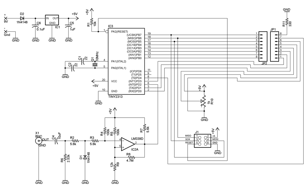
Schematics
Hello
Everything is OK…
But without the program is worth nothing ..
Welcome